
Hello, my name is Kim from Thailand. I’m very new to 3D printing, and this watch is my first project to start experimenting with 3D printing.
Let’s get started. I found this interesting project from printables.com It looks challenging. Because it involves using a variety of skills in one project. including experimenting with 3D printing, coding, and putting it together.
In this blog, I will share the experience of making this watch in 5 parts.
- 3D printing
- Electronic equipment that must be used
- Assembly
- Programming
- Problems encountered and ways to solve them

3D printing
You can download files from printables.com or instructables.com Which I recommend that you download these files from instructables.com is better.
because on printables.com There are still some parts files missing that have not been updated. (2nd back piece)
As for downloading the STL file for printing, you can read the details from the website I recommend downloading. It will tell you the number of pieces to be printed and complete with basic, helpful developer instructions.
Here are some suggestions from my experience.
- Segment Printing

The original file is perfectly done. Everything fits together perfectly. But it caused some problems during assembly. Due to the fit of the work piece
These things cause the segment parts, when assembled with the servo, to cause the servo to work too hard or to move the segment parts out too difficult.
You can solve the problem by sanding or filing it, but these things are a waste of time. Because we have to do this with 30 pieces.
Tips: In the Slicer program, I reduced the size of all segments to 98%, which when assembled still looks beautiful on the front panel of the watch and makes the servo easier to work with.
- Gear
The gears in the prototype are designed When I try to print it and actually use it. I think the gear is not suitable for the gear size of the servo, causing the gear to rotate freely and not move the segment parts out or back in.
I solved the problem by designing a new gear. that can fit snugly with the gears on the servo Makes the servo work at its full potential. I tried using it with a standard 9 gram servo from several brands and it worked well.
and in my project I assembled this gear on to all 30 servos without the help of screws. which reduces working time quite a lot.
However, I have uploaded the gears that I designed on the printables.com You can click to download.

Electronic equipment that must be used
For all the equipment you need for assembly Consisting of the following equipment
- Arduino Mega — The brain
- Arduino Mega Sensor Shield — The I/O
- DS3231 or RTC clock breakout — To keep track of time
- 30 Servos (9 Gram servo) — To move each segment
But on the part of the developers did not recommend a power supply for the main board. and the board with the sensor shield Both boards require a power supply.
Especially then For use of up to 30 servos, we need a certain amount of power for smooth operation. The Arduno uses 5 volts and requires a combined current of not less than 5 amps for both boards.
I don’t have a power adapter. 5 volts with such high amps, So I used the 12 volt 8 amp adapter and used a circuit (DC to DC stepdown) to reduce the power down to 5 volts which worked well for the project.

Assembly
Assembly was the most fun part of this project for me. Many problems occurred during assembly. I would like to introduce some problems and solutions that I encountered throughout this project.
First you need to determine which part is the top when assembling. And which part will be the base when the clock is assembled? This involves sequencing the parts and programming the servo positions in the program.
in my project I set the assembly direction to be like this. Because I need space to make a clock base.
Position of assembly
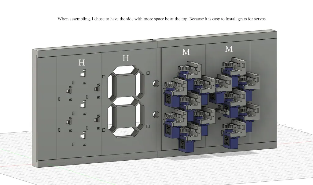
And when I assembled it, I flipped it 180 degrees vertically. so that the side with more space is at the bottom. Because I need space to install the base of the clock.
Normal position when viewed from behind

Tips: When you attach the servo parts to the back plate Pressing down firmly can be difficult. If you press with your hand, I believe you may hurt your hand.
The easiest method I use. I use an F-clamp. by a clamp between the servo and the front end Gently rotate the F-clamp until the servo assembly is snug against the workpiece.
Programming
Location of the servos to be connected to the board.
You can connect the servos to the board by following the numbers in the picture.
For example, You want to continue the first digit of the minute position. (Far right when viewed from the front) In the manual this is designated pin number 2. You connect servo number 1 to pin number 2 and so on. When you do this correctly, servo number 7 will be connected to pin. Number 8
You can see the location of the first pin in the line of code that says
const int DIGIT_STARTING_SEGMENT_INDEX[4] = {2, 9, 22, 29};In the original, there is a section to define the display of numbers in the program in this section.
const int DIGIT_TO_SEGMENT_MAPPING[10][7] = {
  { 1, 1, 1, 1, 1, 1, 0 }, // 0
  { 0, 1, 1, 0, 0, 0, 0 }, // 1
  { 1, 1, 0, 1, 1, 0, 1 }, // 2
  { 1, 1, 1, 1, 0, 0, 1 }, // 3
  { 0, 1, 1, 0, 0, 1, 1 }, // 4
  { 1, 0, 1, 1, 0, 1, 1 }, // 5
  { 1, 0, 1, 1, 1, 1, 1 }, // 6
  { 1, 1, 1, 0, 0, 0, 0 }, // 7
  { 1, 1, 1, 1, 1, 1, 1 }, // 8
  { 1, 1, 1, 1, 0, 1, 1 }  // 9
};
If you assemble as I did, choosing the side with more free space as the base. You need to change the number display code as follows.
const int DIGIT_TO_SEGMENT_MAPPING[10][7] = {
  { 1, 1, 1, 1, 1, 1, 0 },  // 0
  { 0, 1, 1, 0, 0, 0, 0 },  // 1
  { 1, 0, 1, 1, 0, 1, 1 },  // 2
  { 1, 1, 1, 1, 0, 0, 1 },  // 3
  { 0, 1, 1, 0, 1, 0, 1 },  // 4
  { 1, 1, 0, 1, 1, 0, 1 },  // 5
  { 1, 1, 0, 1, 1, 1, 1 },  // 6
  { 0, 1, 1, 1, 0, 0, 0 },  // 7
  { 1, 1, 1, 1, 1, 1, 1 },  // 8
  { 1, 1, 1, 1, 1, 0, 1 }   // 9
};
RTC DS3231
DS3231 is a circuit for displaying real-time time. You can connect it to the sensor shield board with the SDA pin connected to pin number 20 and the SCL pin connected to pin number 21.
You need to connect DS3231 into the circuit before uploading the code to the board. In order for the display to be done correctly
Tips : The program will initially run as a countdown. You can assemble the servo panels one at a time and try uploading the code to see how the servos work. whether it works correctly or not
I recommend that you do it one panel at a time and keep uploading the code. You will be able to find errors precisely. And it’s easier to fix it.
Problems encountered and ways to solve them
#1 Swap countdown to clok
Find this line of code.
String stringCount = String(count); // Swap to timeString to use the clock.Then change it like this
String stringCount = String(timeString);#2 Setting time for DS3231
Under the line RTC.BEGIN Add the following code.
void setup() {
  rtc.begin();
  rtc.setDOW(SUNDAY);
  rtc.setTime(20, 22 ,0); //24 hour format ex 20:22:00
  rtc.setDate(18, 2, 2024);
After that, you click to upload the code to the board. Once you have uploaded the code, DS3231 It will remember the upload time and move forward continuously.
Delete the time setting. and upload again If you do not delete the time settings Your time will always be uploaded to the set time.
Employee / Son / Father / Husband / and a little of everything in between